Tablet compression machines are designed with consideration for the types of dies and punches that will be utilized on them. The arrangement of dies and punches on a compression machine is referred to as tooling, which is primarily classified into B and D categories.
The B tooling dies and punches can further be specified as BB, while D tooling can also include dies and punches that can be employed on a B tooling machine, which is known as DB.
Primarily, there are two standards, i.e. D and B, in the US specification as outlined in the Tableting Specification Manual (TSM), whereas in Europe, the European standard referred to as the EU, or “Euronorm” standard.
While the specifications are quite similar, the two are fundamentally distinct.
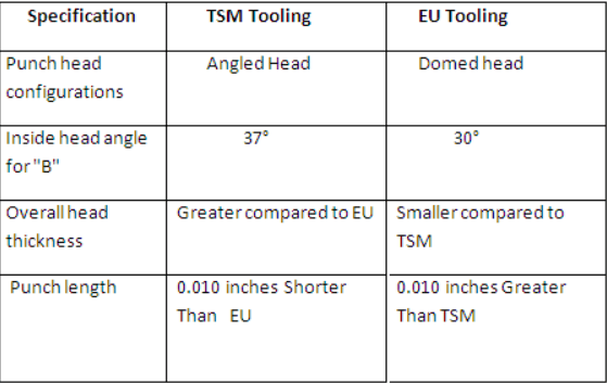
Following is the key difference between D and B tooling for tablets compression
D Tooling:
- Barrel Diameter is 1 inch
- Head Diameter is 1 and ¼ th inch length is 5.25 inch
- Dies outer diameter is 0.945 and
BB Tooling:
- Barrel Diameter is 0.75 inch
- Head Diameter is 1 inch length is 5.25 inch
- Dies outer diameter is 30.16 mm
B tooling is identical to BB; the only distinction is that the lower punch length measures precisely 3 and 9/16 inches long.
D tooling dies and punches typically possess a thicker diameter or a larger diameter for both their body and the tips of the punches. Additionally, the outer diameter of D type tooling dies is greater compared to that of B type tooling, rendering D type tooling dies and punches appropriate for compressing larger size tablets as the tip of the pinches is border compared to B tooling dues and punches.
Many subcategories like DB, BB type tablets dies and punches are made depending up on the punches and dies requirement of product.
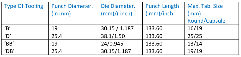
The table below will aid in comprehending the concept of tablet tooling and its classification into B and D tooling, as well as BB and DB tooling.
Following definitions for direct terminology for tooling (Punches and dies).
1. Head: The termination of the punch that directs it through the cam track of the tablet machine during its rotation.
2. Head flat (Dwell Flat): The flat section of the head that absorbs the compression force from the rollers (in upper punches) and determines both the weight and the ejection height (in lower punches).
3. Outside head Angle: The region that makes contact with the roller before the head flat during compression.
4. Inside Head Angle: This area is responsible for pulling down the lower punches after ejection and raising the upper punches following compression.
5. Neck: The relieved section situated between the head and barrel, which allows for clearance for the cams.
6. Barrel: This section guides the punch (during its upward and downward movement) in relation to the turret guides.
7. Stem: This refers to the section of the punch that is opposite the head, starting from the tip and extending to the point where the full diameter of the barrel commences. If a chamfer is present, the barrel typically attains its full diameter just above the chamfer.
8. Tip: This component defines the size, shape, and profile of the tablet.
9. Tip face: This portion of the punch is where the tablet is formed. A good surface finish is essential here to ensure the production of quality tablets.
10. Working length: The distance from the bottom of the cup to the head flat is referred to as the working length, which determines the weight and thickness of the tablet.
11. Overall length: This is the distance from the top of the cup to the head flat.
12. Key Angle: This describes the relationship between the punch key and the tablet shape. The position of the key is influenced by the tablet shape, take-off angle, and turret rotation.
13. Domed Heads: These increase the dwell time, thereby contributing to improved tablet hardness.
14. Dwell time: This is the duration for which the punches remain below the pressure roller while rotating in the machine.
15. Clearance: The clearance is calculated as die bore diameter minus punch tip diameter.
16. Hardness: Typically assessed using the HRC (Rockwell ‘C’ scale), with optimal readings as follows:
STEEL HARDNESS
- OHNS O1 58-59
- HCHC D2 59-60
- HCHC D3 61-62
Generally, the following combinations are employed.
- For punches AISI O1 (OHNS)
- For dies AISI D3 (HCHC)
- For highly abrasive products AISI D2 (HCHC) punches
Die: hardened steel (HCHC) mold utilized to form the shape of a tablet.
Die Terminology:
- Die O.D.: The external diameter of the die, which must be compatible with the die pockets in the press.
- Die Height: The total height of the die. ‘B’ Tooling – 22.225 mm ‘D’ Tooling – 23.820 mm ‘BB’ Tooling – 22.225 mm
- Die Bore: The cavity where the tablet is produced. The shape and size of the cavity dictate the form of the tablet.
- Chamfer: The entry angle of the die bore.
- Taper dies: Dies featuring a tapered bore on one or both ends, facilitating the easy ejection of tablets (primarily for double-layered tablets).
- Die Groove: The groove encircling the die’s periphery, which enables the die to be secured in the press.
- Lined (Insert) Dies: Dies equipped with a linear insert composed of a significantly harder, more wear-resistant material such as tungsten carbide and ceramic.
Made of tooling:
- OHNS: – Oil-hardened non-sticky stainless steel
- HCHC: High chromium High Carbon
- Punch standard: Europe, Japan, TSM